Figure 2. Scheme 2: Flow path consisted of IGV, R1, S1, R2, EGV
Analysis of Three-dimension Viscous Flow in the Model Axial Compressor Stage K1002L

K Tribunskaia and Y V Kozhukhov

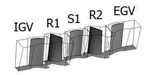
Abstract. The main investigation subject considered in this paper is axial compressor model stage K1002L. Three simulation models were designed: Scheme 1 – inlet stage model consisting of IGV (Inlet Guide Vane), rotor and diffuser; Scheme 2 – two-stage model: IGV, first-stage rotor, first-stage diffuser, second-stage rotor, EGV (Exit Guide Vane); Scheme 3 – full-round model: IGV, rotor, diffuser.

Numerical investigation of the model stage was held for four circumferential velocities at the outer diameter (Uout=125,160,180,210 m/s) within the range of flow coefficient: φ = 0.4 – 0.6. The computational domain was created with ANSYS CFX Workbench.

According to simulation results, there were constructed aerodynamic characteristic curves of adiabatic efficiency and the adiabatic head coefficient calculated for total parameters were compared with data from the full-scale test received at the Central Boiler and Turbine Institution (CBTI), thus, verification of the calculated data was carried out. Moreover, there were conducted the following studies: comparison of aerodynamic characteristics of the schemes 1, 2; comparison of the sector and full-round models.

The analysis and conclusions are supplemented by gas-dynamic method calculation for axial compressor stages.

Далее

Figure 1. Solid model NASA rotor 37 stage
Analysis of casing treatment`s impact on the axial compressor model stage characteristics

K Tribunskaia and Y V Kozhukhov

Abstract. There are special requirements for the compressors of aircraft engines. They must ensure maximum efficiency in a maximally large stable work zone Due to a high pressure ratio these stages are more susceptible to the losses from radial clearance. One of the approaches to reduce such losses is the application of above-rotor devices. In the following study there is considered the impact of such treatments on the compressor stage performance. Despite the fact that there is a sufficient amount of research about this issue, their results are contradictory. The use of these devices can affect the characteristics of compressor stage performance both positively and negatively. This study was conducted using the methods of computational fluid dynamics and was based on the NASA Rotor-37 geometry model stage. Results were obtained through the comparison of the characteristics of stages with and without above-rotor devices.

Далее

Figure 5. The influence of the inlet boundary location for the high-pressure impeller (IMP2)
Optimization of a centrifugal compressor impeller using CFD: the choice of simulation model parameters

V V Neverov, Y V Kozhukhov, A M Yablokov, A A Lebedev

Abstract. Nowadays the optimization using computational fluid dynamics (CFD) plays an important role in the design process of turbomachines. However, for the successful and productive optimization it is necessary to define a simulation model correctly and rationally. The article deals with the choice of a grid and computational domain parameters for optimization of centrifugal compressor impellers using computational fluid dynamics. Searching and applying optimal parameters of the grid model, the computational domain and solver settings allows engineers to carry out a high-accuracy modelling and to use computational capability effectively. The presented research was conducted using Numeca Fine/Turbo package with Spalart-Allmaras and Shear Stress Transport turbulence models. Two radial impellers was investigated: the high-pressure at ѱT=0.71 and the low-pressure at ѱT=0.43. The following parameters of the computational model were considered: the location of inlet and outlet boundaries, type of mesh topology, size of mesh and mesh parameter y+. Results of the investigation demonstrate that the choice of optimal parameters leads to the significant reduction of the computational time. Optimal parameters in comparison with non-optimal but visually similar parameters can reduce the calculation time up to 4 times. Besides, it is established that some parameters have a major impact on the result of modelling.

Далее

Fig. 1 The design procedure
Development of the virtual experimental bench on the basis of modernized research centrifugal compressor stage test unit with the 3D impeller

A A Aksenov, A M Danilishin, А М Dubenko, Y V Kozhukov

Abstract. Design modernization of the centrifugal compressor stage test bench with three dimensional impeller blades was carried out for the possibility of holding a series of experimental studies of different 3D impeller models. The studies relates to the problem of joint work of the impeller and the stationary channels of the housing when carrying out works on modernization with the aim of improving the parameters of the volumetric capacity or pressure in the presence of design constraints. The object of study is the experimental single end centrifugal compressor stage with the 3D impeller. Compressor stage consists of the 3D impeller, vaneless diffuser (VLD), outlet collector — folded side scroll and downstream pipe. The drive is a DC motor 75 kW. The increase gear (multiplier) was set between the compressor and DC motor, gear ratio is i = 9.8. To obtain the characteristics of the compressor and the flow area the following values were measured: total pressure, static pressure, direction (angles) of the stream in different cross sections. Additional pneumometric probes on the front wall of the VLD of the test bench have been installed. Total pressure probes and foster holes for the measurement of total and static pressure by the new drainage scheme. This allowed carrying out full experimental studies for two elements of centrifugal compressor stage. After the experimental tests the comprehensive information about the performance of model stage were obtained. Was measured geometric parameters and the constructed virtual model of the experimental bench flow part with the help of Creo Parametric 3.0 and ANSYS v. 16.2. Conducted CFD calculations and verification with experimental data. Identifies the steps for further experimental and virtual works.

  Далее

Figure 6. The basic diagram of the air supply for reconstruction 1, 2, 3 - the main compressor units with frequency converters, and built-in coolers and moistures; 4 - Reserve compressor unit; 5, 6, 7 - drying units with a fine filter; 8 - 24 - stop valves; 25 - Check Valve
The methodology for the existing complex pneumatic systems efficiency increase with the use of mathematical modeling

A.M. Danilishin1, S.V. Kartashov1, Y.V. Kozhukhov1 and E.G. Kozin2

Absrtact. The method for the existing complex pneumatic systems efficiency increase has been developed, including the survey steps, mathematical technological process modeling, optimizing the pneumatic system configuration, its operation modes, selection of optimal compressor units and additional equipment. Practical application of the methodology is considered by the example of the existing pneumatic systems underground depot reconstruction. The first stage of the methodology is the survey of acting pneumatic system. The second stage of technique is multivariable mathematical modeling of the pneumatic system operation. The developed methodology is applicable to complex pneumatic systems.

Далее

ARE THERE ANY QUESTIONS LEFT?

Call us: +7 (812) 715-41-64
or leave the request and get the advice from our expert